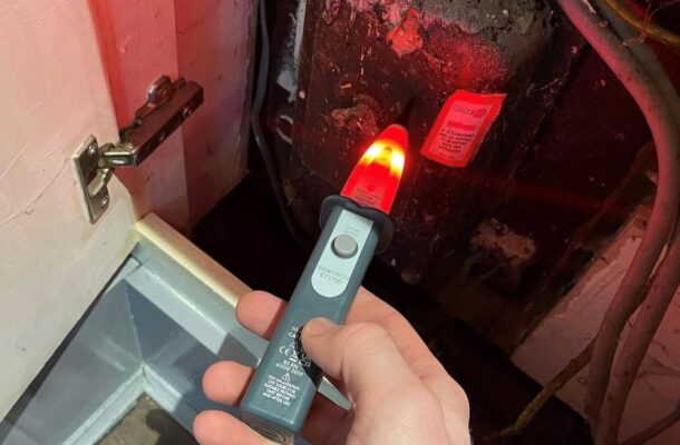
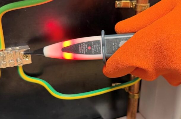
Your 12 Step Guide to Safe Isolation.

WHY DO WE NEED A SAFE ELECTRICAL ISOLATION PROCEDURE?
To ensure that any item of electrical equipment or plant is electrically disconnected from all sources of electrical supply, to prevent danger to anyone who needs to work on or near it!
THE CONSEQUENCES OF FAILING TO UNDERTAKE SAFE ELECTRICAL ISOLATION CAN BE LIFE CHANGING OR FATAL!

Safe Isolation: A Practical 12-Step Procedure
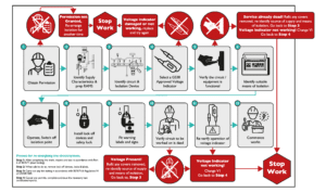
Safe isolation is a fundamental part of electrical work. Before working on or near electrical equipment, the objective is simple: ensure that the equipment is disconnected from all sources of electrical supply and cannot inadvertently become energised while work is taking place.
However, simply switching off a circuit breaker isn’t enough. A safe isolation procedure should positively identify the correct circuit, secure the means of isolation and, crucially, prove that the circuit is dead at the point of work.
Here are the 12 steps to follow.
-
Obtain permission
Before isolation, check with the Duty Holder or Senior Engineer that the circuit or equipment can safely be isolated. Consider what else may be affected by the shutdown before proceeding.
-
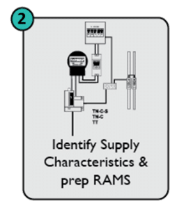
Identify the supply characteristics
Establish the type of supply and therefore which conductors need to be isolated. The procedure distinguishes between TN-S/TN-C-S systems, where phase isolation is identified, and TT systems, where all live conductors are to be isolated. Appropriate risk assessment and method statements should also be in place.
-
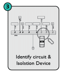
Identify the circuit and isolation device
Locate and positively identify the circuit or equipment being worked on and its means of isolation. Check for alternative sources of supply, using drawings, schematics and labelling where necessary.
-
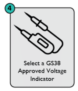
Select the correct voltage indicator
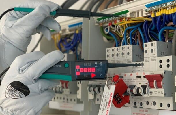
Use a suitable two-pole voltage indicator complying with BS EN 61243-3 and GS38 requirements. (For more information on what makes a GS38 compliant voltage tester click here). Inspect its condition before use and verify that it operates correctly using a proving unit.

KT1780 two-pole voltage indicator from Kewtech
-
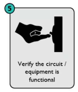
Verify that the circuit is functional
Before isolation, establish that the circuit or equipment is live and functioning. If it is already dead, don’t simply assume you’ve found the correct circuit – refit any covers removed and re-identify the source of supply and means of isolation.
-
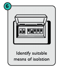
Identify a suitable means of isolation
Confirm that the selected isolation point is suitable for the purpose. The guide specifically refers to the definition of isolation within BS 7671 Table 537.4.
-
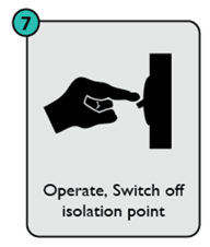
Switch off the isolation point
Operate the identified device to disconnect the circuit or equipment from its supply.
-
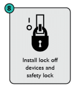
Lock off the isolation device
Fit an appropriate lock-off device and safety lock to prevent the supply being inadvertently restored. The person carrying out the work should retain control of the safety-lock key. To view Kewtech’s comprehensive range of lock-off devices and kits click here.
-
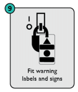
Fit warning labels
Place an appropriate caution notice at the point of isolation so others are aware that the circuit has been deliberately isolated and must not be re-energised.
-
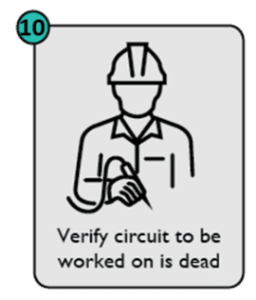
Prove dead at the point of work
This is a critical part of the procedure.
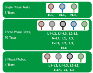
Using the BS EN 61243-3 voltage indicator, test between all relevant conductors at the actual point where work will take place. The required tests depend on the circuit.
For a single-phase circuit, the guide specifies three tests: L-E, L-N and N-E.
For a three-phase circuit with neutral and earth, it specifies ten: L1-L2, L1-L3, L2-L3, N-L1, N-L2, N-L3, E-L1, E-L2, E-L3 and N-E.
For a three-phase motor, six tests are shown: the three phase-to-phase combinations and each phase to earth.
The required result is 0V at the point of work.
-
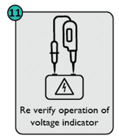
Re-prove the voltage indicator
Once the circuit has been proved dead, test the voltage indicator on the proving unit again. This confirms that the indicator was still functioning correctly when the dead test was performed.
If it fails this second check, the previous result cannot be relied upon: stop work, select another voltage indicator and repeat the process.
This is the basis of the important PROVE – TEST – PROVE principle.
-
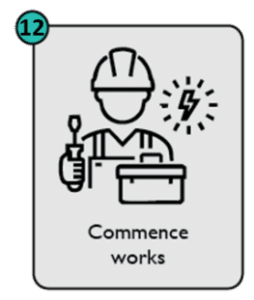
Commence work – but remain vigilant
Safe isolation doesn’t end when the tools come out. Remain alert to other potential sources or inputs, including borrowed neutrals and control inputs. The guide also recommends rechecking with the voltage indicator and proving device if you leave the circuit or equipment and subsequently return to it.
Safe isolation is more than switching off!
A robust safe isolation procedure provides a systematic way of establishing that the correct circuit has been identified, isolated, secured against reconnection and proved dead where the work is actually taking place.
The key principle to remember is simple: never assume a circuit is dead. Prove it.
The 12-step procedure in Kewtech’s On-Site Guide to Safe Isolation Procedures is based on the process recommended by the HSE and Electrical Safety First’s Safe Isolation Best-Practice Guide – 4th Edition.
Interested in learning more? Here are some relevant articles…
Is your equipment GS38 compliant?
Stop using your multimeter for proving dead!
More News Articles
2 Feb 2026
Is your equipment HSE GS38 compliant?
23 Feb 2026
Stop using your Multimeter for proving dead!