Show me information on:
For helpful information on correct safe isolation procedure and it’s importance click here.
Download 12 step Lock off procedure
A function of a tester to automatically select the appropriate measuring range based on the input signal.
The average of an AC waveform’s instantaneous values taken over a half cycle. Ordinary testers respond to the average value.
For sinusoidal wave :
Average value = Maximum value×2/π = Maximum value×0.637
When the true RMS value is 100V ;
Average value= Maximum value×2/π =141×0.637 = 90(V)
The reading of ordinary testers is calibrated in terms of the effective value of a sinusoidal wave even though they are responding to the average value. They are called average-responding-RMS-calibrated type of testers. As opposed to these, true-RMS type testers respond and show the true RMS value.
A function to freeze the reading on a digital display for ease of checking or recording even in a difficult-to-read situation for a tester.
A unit used to express the magnitude of change in level of electric signal or sound intensity.
A voltage ratio of 1 to 10 is equal to -20dB, 10 to 1 to 20dB, 100 to 1 to 40dB and 1000 to 1 to 60dB. A power ratio of 10 to 1 is not 20dB, but 10dB, since power(P) is proportional to the square of voltage(V).
A function to apply a diode or a transistor a constant current having a value needed to turn it on in order to check the diode’s or the transistor’s forward voltage drop and identifying the connection direction of the device.
A degree of distortion of a waveform, typically expressed as the ratio of the effective value of harmonic components to the effective value of the fundamental component.
A technique to convert voltage into time. The first integration time (Ts) and the second integration time (Tx) are used. First, the input voltage (Vx) is integrated on a certain time interval (Ts) and then, the resulting voltage is “reverse-integrated” using a reference voltage (Vr) until it becomes 0 (zero).
The “reverse-integration time” (Tx) is proportional to input voltage (Vx). Therefore, the input voltage (Vx) can be determined by measuring Tx.
With this technique, stable measurements can be taken with high accuracy, resolution and noise rejection ratio. One particular advantage is high noise rejection ratio at 50 or 60Hz power line frequency. All of Kyoritsu digital clamp meters and testers utilize this method.
Principle of Earth Resistance Measurement
| This instrument makes earth resistance measurements with fall-of-potential method, which is a method to obtain earth resistance value “Rx” by applying AC constant current “I” between the measurement object “E” (earth electrode) and “H(C)” (current electrode), and finding out the potential difference “V” between “E” (earth electrode) and “S(P)” (potential electrode). | 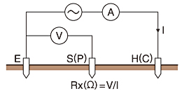 |
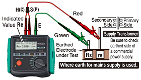
| Simplified Measurement (2-Wire) |
Precise Measurement (3-Wire) |
 |
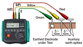 |
| 2-Wire Earth Resistance Measurement | 3-Wire Earth Resistance Measurement |
|
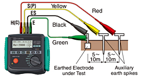
Precise Measurement (4-Wire) |
|
 |
|
| 4-Wire Earth Resistance Measurement |
Ghost voltage, or phantom voltage, is a term used to describe capasitive coupling between energised wiring and adjacent unenergised wiring.
When current flows through a conductor, it produces a magnetic field which in turn can produce voltage in another nearby conductor. If an energised circuit is in close proximity to an unenergised one, such as in the same conduit, then this can form a capacitor allowing capacitive coupling between the adjacent wiring.
If this unenergised conductor has an open neutral then this voltage will be stored here until a path to neutral is provided. When a path to neutral is provided, any ghost voltage will bleed off instantly so it cannot be used to power a load.
The KT1795 two pole tester has a ghost voltage clearance feature which dissipates any ghost voltage so that you know you are getting an accurate indication of any potentially dangerous voltage being present or not.
When a current-carrying conductor is placed in a magnetic field so that the direction of the magnetic field is perpendicular to the direction of the current flow, voltage is developed in the direction perpendicular to both the magnetic field and the current flow. This is called the Hall effect and the Hall element is a device that utilizes the effect.
Kyoritsu AC/DC clamp meters and clamp sensors employ the Hall element.
Power line AC voltage from a utility company has near sinusoidal waveform of fundamental frequency with little distortion. When only a load consisting of resisters, capacitors and coils, called a linear load (its constant is fixed regardless of the amount of current flowing through it), is connected to mains supply, no distortion is introduced into the load current waveform. However, when a non-linear load, such as a semiconductor and a saturable reactor, is connected, distortion appears in the load current waveform. The current with a waveform containing distortion, or harmonic current, flows in the direction toward the low impedance side and in the process, produces voltage drop over the impedance of the current path, causing the load voltage also to contain harmonics.
A function to memorize the peak value over a certain period of time.
Reading in the peak hold mode is the peak current value multiplied by 1/√2.
(When the input is sinusoidal, the reading is equal to the true RMS value.)
The value at a point where a waveform has the maximum amplitude.
The minimum increments in which a tester can take measurements.
Frequency at which an A/D converter circuit senses the quantity to measure: typically, twice or three times per second.
Also referred to as electric shock. When a person touches a motor that has a “leak”, a path can be created from the motor frame to the hand, body and feet of the person to the floor he is standing on to allow a current to flow through it, sometimes resulting in a fatal accident.
The seriousness of a shock hazard widely varies depending on the amount and duration of the current that flows through the person’ s body. His constitution, age and medical condition are also variation factors, but in general, at a frequency of 50 or 60Hz, stimulus to the skin is felt at 1mA, considerable pain occurs at 5mA, pain is unbearable at 10mA, there is difficulty in releasing the “leaking” object because of intense muscle contraction at 20mA, it is considerably dangerous at 50mA and fatality is likely at 100mA.
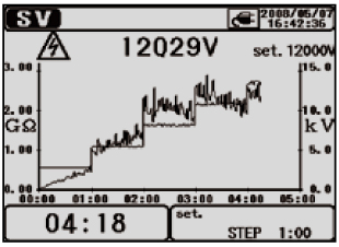
This is a test based on the principle that an ideal insulation will produce identical readings at all voltages, while an insulation which is being over stressed, will show lower insulation values at higher voltages. During the test, the applied voltage incrementally steps by a certain voltage taking successive 5-time measurement. Degradation of insulation may be doubted when insulation resistances become lower at higher applied voltages.
Ex: SV display of KEW 3128
A device that uses the voltage developed by the junction of two dissimilar metals to measure temperature. One junction, called the measuring junction, is placed at the point where temperature is to be measured. The other junction, called the reference junction, is maintained at a reference temperature. The voltage developed between the two junctions varies depending on the difference between the temperatures of the two junctions and the type of thermocouple.
Most alternating currents and voltages are expressed in effective values, which are also referred to as RMS(Root-Mean-Square)values. The effective value is the square root of the average of the square of alternating current or voltage values.
Many clamp meters with rectifier type circuits have scales that are calibrated in RMS values for AC measurements. But, they actually measure the average value of input voltage or current, assuming the voltage or current to be a sine wave.
The conversion factor for a sine wave, which is obtained by dividing the effective value by the average value, is 1.1. These instruments are in error if the input voltage or current has some other shape than a sine wave.
CF : Crest Factor = Peak value/RMS value
DC = 1
Sine wave = 1.414