Amendment 4 Changes to Testing in a Medical Location
Amendment 4 Changes to Testing in a Medical Location
Introduction
The IET Wiring Regulations is the safety standard for fixed low voltage(LV) electrical installations and are designated as British Standard 7671. The standard contains 8 Parts and 14 Appendices. Parts 1 to 6 and Part 8 are known as the general requirements and they apply to all LV installations, where relevant.
Part 7 Special installations or locations
Part 7 supplements and modifies the general requirements set out in Parts 1 to 6 and Part 8 where there are additional risks to the safety of people using the installation. For example, 701 locations containing a bath or shower and 702 swimming pools and other basins, have additional risks of shock to persons in those locations. This is due to the fact that they will be wet and have large areas of bare skin exposed, so additional measures have to be taken to prevent shock.
Section 710 Medical Locations
This section applies to patient healthcare facilities, such as hospitals, private clinics, medica land dental practices, health care centres, and dedicated medical rooms in workplaces to provide for the safety of patients and medical staff. The risks to patients are enhanced as they will often be sick, injured or anaesthetised. Of particular risk are operating theatres, which are known as Group 2 medical locations.
In a Group 2 location, the patient may be directly connected to Medical Equipment (ME) which is usually connected to a 230V supply. This ME is intended for life support, surgical applications and monitoring. ME equipment has a high level of separation from the equipment incoming supply. The highest risks are where surgical equipment is used inside the body for intracardiac and brain surgery.
Additional protection is provided for the ME by providing special sockets for the supply of this equipment. These sockets have to be coloured blue, unswitched and be supplied from a medical IT system. The medical IT system is in a cabinet situated close the operating theatre. The IT cabinet has a special isolating transformer to isolate the IT output from the supply earthing system. The output circuits are protected by an insulation monitoring system and double pole circuit breakers. The supply conductors, which should both be coloured brown as they do not have a neutral, supply the blue sockets. The supply conductors should be fire resistant for at least 1 hour.
Earthing and supplementary equipotential bonding
In addition to connections to the installation to reduce touch voltages an earth bonding bus bar (EBB), see Image 1, has to be installed in, or adjacent to, the operating theatre. The EBB is connected to the IT cabinet earthing system. Supplementary bonding conductors are then run out to the blue sockets, supplementary equipotential bonding points, extraneous-conductive parts unless they are intended to be isolated from earth, conductive floor grids and mats.
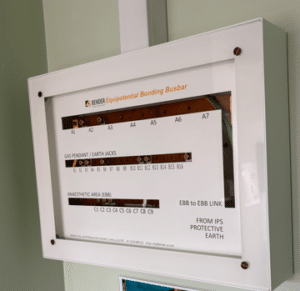
Image 1. Earth Bonding Bus Bar
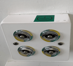
Image 2. Supplementary equipotential bonding connection bonding points
Changes to the IET Wiring Regulations
On the 15th of April 2026, an updated edition of the IET Wiring Regulation, BS 7671:2018 +Amendment 4 :2026 was published.
This new edition contains an extensive rewrite of Section 710. There is a new requirement in Regulation 710.643.1.201 (d). which says: –
The resistance of each individual supplementary bonding conductor shall be recorded and included in the documentation set out in regulation 710.514.9.101.
With this in mind, there is a model form is provided at Annexe B710 to record the test results.
Critically, the test result must meet the requirement set out in Regulation 710.415.2.102 which is not to exceed 0.2Ω.
There is an existing requirement in Regulation 710.415.2.102 which requires a test to be carried out between simultaneous accessible exposed conductive parts where the test resistance shall not exceed 0.2Ω.
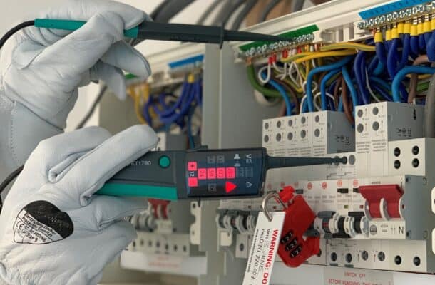
Carrying out the new test for supplementary equipotential bonding continuity
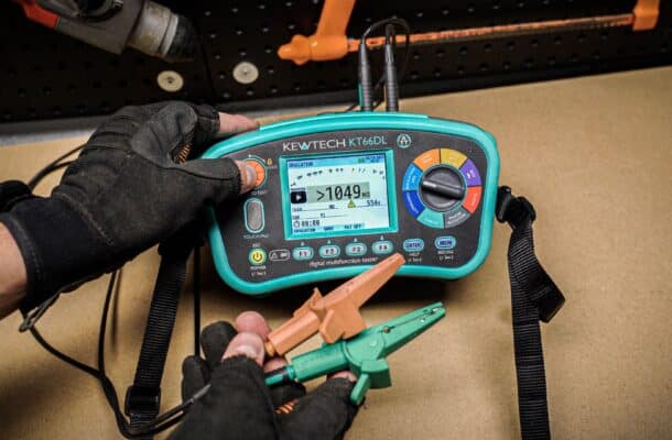
Firstly, a good quality low resistance test meter that meets the requirements set out in Regulation 643.1 which sates the instrument must meet the requirements of the relevant sections of BS EN 61557. The Kewtech KT66DL meets that requirement for continuity testing together with a full range of other installation tests.
The meter and test leads need to be inspected to ensure that they are undamaged and in good condition. Moreover, it should be verified before testing commences that the meter batteries are charged and the meter has a current calibration certificate.
A long continuity test lead will be required to perform the test, the Kewtech ACC50MTL 50m R2 Test Lead is ideal for this purpose.
Critically, the installation should not be in service or energised for this test as the test for safety reasons.
In addition, to avoid breaking infection control seals on the blue IT sockets a socket adaptor will be required. The KEWCHECK R2 socket adaptor provides a safe and convenient way of making the required test.
Firstly, the meter should be switched on and the continuity test range should be connected. Secondly, the long lead should be connected to one test terminal and a short test lead to the other terminal. Following this, the combined lead resistances should then be nulled out before the testing commences.
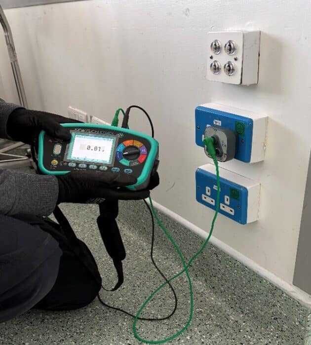
The long lead should then be connected to the incoming earth terminal of the EBB, see image 3.
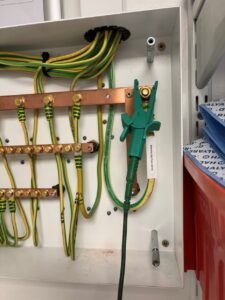
Image 3. Connection of the test lead to the EBB.
- The inspector can then set off around all the points connected to each of the individual supplementary bonding conductors connected to the EBB recording the results as they go. See Image 4.

Image 4. Testing for continuity at an IT socket.
If any test result exceeds 0.2Ω then it should be reported for to the duty holder for the installation or person ordering the work for further investigation and rectification.
More News Articles
23 Mar 2026
The best MFT on the market?