CHANGES TO INSPECTION AND TESTING IN AMENDMENT 2 OF THE WIRING REGULATIONS
Last year the British Standards Institute (BSI) published the Draft for Public Consultation (DPC) for the proposed Amendment 2 to the 18th Edition of British Standard 7671, this is more commonly known as the 18th Edition of the Wiring Regulations. The public were given the opportunity to read the proposed new Wiring Regulations and comment on any proposed changes. That DPC process closed on the 11th of December 2020. Those comments and proposals from the public are being considered by the Institution of Engineering and Technology (IET). This article looks at the proposed changes in the DPC that will impact on inspection and testing of electrical installations. However, it will not be known what changes to the DPC will be made until Amendment 2 is published by the IET. The expected publication date is 28th March 2022.
It is expected, as usual for a new edition, there will be an overlap period where new installation can be designed to the old BS 7671:2018 Amendment 1:2020 or, the new Amendment 2 which can be used from the date of publication. When issuing electrical installation certification, it is important to state which edition of the Wring Regulations has been used for verification. The DPC has a new Electrical Installation Certificate (EIC) model form in Appendix 6. Regulation 642.3 still lists all of the inspections that have to be carried out for the Initial Verification process. However, Inspectors will be pleased to see confirmation of the inspections that are satisfactory have been reduced from 73 to 13 tick boxes. The model form in Appendix 6 for the Schedule of Test Results has an additional 3 columns making a total of 28 possible entries for a single circuit. The additional 3 columns are for recording the BS or BSEN for the of RCD protecting a circuit, the Type of RCD and load current rating of the RCD. The existing single column for recording of the RCD disconnection time remains.
Many European countries have already mandated the use of Type A RCDs in preference to ordinary Type AC devices. Regulation 531.3.3 describes the functionality of the different types of RCD and how the correct type should be selected. The DPC makes a new requirement in this regulation that only permits the use of Type AC RCDs to protect circuits where it is known that the load contains no DC components. It also provides guidance on circuits that may have no DC components such as heating appliances and/or simple filament lighting which does not include electronic transformers of dimmer controls. The default position will be to fit Type A RCDs which provide tripping under fault conditions on alternating sinusoidal residual currents, suddenly applied or smoothly increasing. Type A RCDs will operate under fault conditions with DC components up to 6mA. The reason for this new requirement is RCDs of Type AC and Type A have ferrite rings with the line and neutral windings wound on the ferrite rings. These ferrite rings operate as a transformer where detection of a difference in line and neutral currents will cause a current to flow a 3rd tertiary winding which trips the RCD. If DC current is imposed on the AC current this will cause a biasing of the ferrite material in the RCD preventing it from acting as a transformer, and hence stopping the RCD tripping under fault conditions. This condition is commonly known as blinding or locking up.
Fortunately, most RCD manufactures have ceased making Type AC RCDs and supply Type A as standard. Some domestic appliance and boiler manufacturers already specify Type A RCDs to protect their equipment.
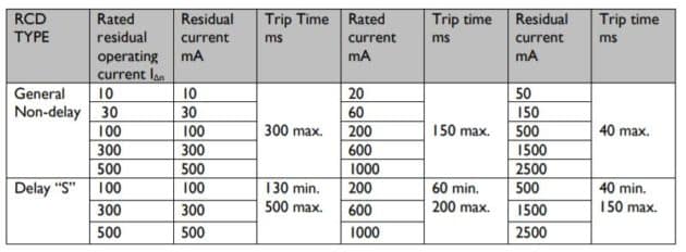
It is important to use an instrument that has the facility to test the Type of RCD installed when testing RCDs. This will involve selecting both the tripping current of the RCD and the Type of RCD installed. There is no guidance on what tripping current and tripping time should be recorded in the single column on the schedule of test results. However, Appendix 4 Table 3A of the Wiring Regulations sets out the performance criteria for RCDs. This table is reproduced below.
It is recommended that where a general RCD is installed for Additional Protection, an RCD not exceeding 30mA, the RCD is tested at a X1 and x5 tripping current on both half cycles of the AC waveform. Where an RCD is installed for Fault Protection it is recommended it is tested at X1 of the tripping current only on both half cycles of the AC waveform. This X1 test should verify that the maximum tripping time measured meets the requirements of Table 41.1 and Regulation 411.3.2.3 and 411.3.2.4 of the Wiring Regulations as appropriate. Where an RCD is installed for fire protection then only a X1 test on both half cycles needs to be carried out. It is recommended that the highest tripping time measured during the appropriate testing sequence is recorded on the schedule of test results.
The DPC for the first time includes a new Part 8 Functional Requirements and a new Chapter 8.2. This new Chapter 8.2 is for Prosumers Low Voltage Electrical Installations.
The term Prosumer is defined in Part 2 of the DPC as an “Entity or party which can be both a producer and consumer of electrical energy”. The installation is then known as a PEI, the Prosumers Electrical Installation. The PEI is also defined in Part 2 as,
“Prosumer’s Electrical Installation (PEI).
Low-voltage electrical installation connected or not to a public distribution network able to operate:
• with local power supplies, and/or
• with local storage units,
and that monitors and controls the energy from the connected sources delivering it to:
• current-using equipment, and/or
• local storage units, and/or
• public distribution network.
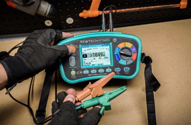
These PEI installations can draw their supplies from the supply network, export energy to the supply network from onsite generation, battery storage. Alternatively, the PEI can be disconnected completely from the supply network. When operating completely disconnected from the supply network, known as “Island Mode”, it also requires disconnection from the supply network means of earthing. There is already a requirement in the Wiring Regulations in Regulation 551.4.3.2.1, where local generation is used as a switched alternative to the public supply, for an alternative suitable means of earthing to be provided. This will require a separate means of earthing to be provided in the form of an earth electrode such as foundation earthing, earth rods, earth mats or earth plates. This means of earthing will need to be tested. If there is a supply already available on site then an earth loop impedance tester can be used to verify the external earth loop impedance (Ze). If there is no supply available on site then an earth resistance test will need to be carried out using an earth resistance tester, test earth electrodes and a long lead set to verify the earth resistance (RA). The Kewtech KT65DL and KT66DL Multi-function testers can perform both of these important tests.
More News Articles