18TH EDITION AMENDMENT 2 CHANGES TO INSULATION RESISTANCE TESTING
18TH EDITION AMENDMENT 2 CHANGES TO INSULATION RESISTANCE TESTING
Need for Insulation Resistance Testing.
The First Edition of the Wiring Regulations in 1882 said.
“The difficulties that beset the electrical engineer are chiefly internal and invisible and they can only be effectively guarded against by “testing” or probing with electric currents. They depend chiefly on leakage, undue resistance in the conductor, and bad joints. Which lead to the waste of energy and the production of heat. These defects can only be detected by measuring, by means of special apparatus, the currents that are neither ordinary or for the purpose of testing, passed through the circuit”.
If we have a look at that early regulation from over 138 years ago, we can see the principles of those early regulations remain as good today for insulation resistance testing as they were all those years ago. Insulation resistance faults are “chiefly internal and invisible” and may result in a “leakage” current flowing to earth. “Testing” and “Probing with electric currents” is not a new activity as the 1882 Regulations mentions this. Today we have extensive requirements in the 18th Edition Amendment 2 of the Wiring Regulations to inspect and test installations. Insulation resistance faults may be detected by, “ special apparatus”, in the form of an insulation resistance tester or an earth leakage clamp meter.
The IET Wiring Regulations 18th Edition Amendment 2.
The latest Edition of the Wiring Regulations, BS 7671 :2018 Amendment 2:2022, was published on the 28th March this year. This new edition has made a significant change to insulation resistance testing of new electrical installations.
The requirement to carry out the tests in sequence has not changed. Insulation resistance testing is the second test in the sequence of tests. The installation should already have been inspected prior to testing. Test instruments are required to be compliant with the relevant parts BS EN 61557, see Regulation 643.1
The first test in the sequence of testing is a test of the continuity of conductors. This is described in Regulation 643.2.1 and requires a satisfactory continuity test of protective conductors, including protective bonding conductors and in the case of ring final circuits, live conductors. If these tests are not satisfactory any defects must be rectified before insulation resistance testing is commenced. It is critical to verify the installation is connected to a means of earthing before commencing insulation resistance testing.
Preparation for carrying out an Insulation Resistance Test.
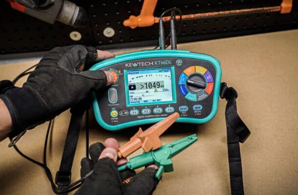
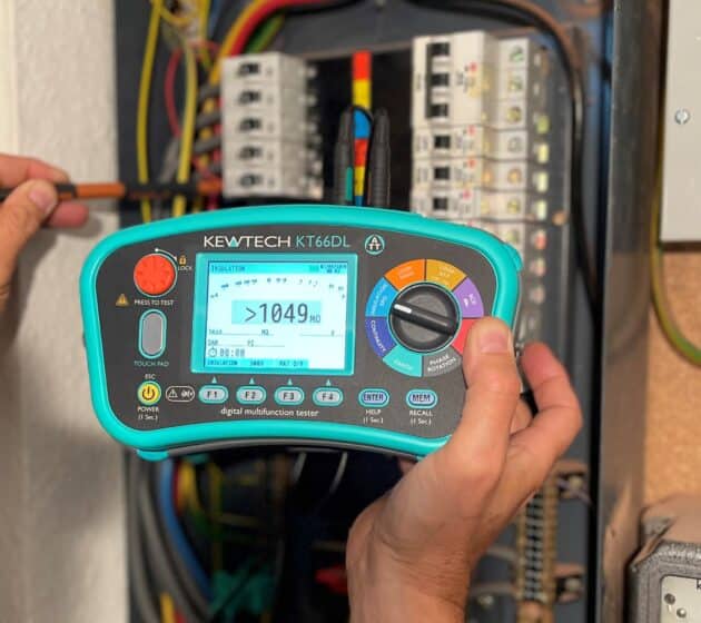
Before starting an IR test ensure the meter you intend to use complies with BS EN 61557-2 and it is undamaged and in good condition. The Kewtech KT66DL MFT meets, and exceeds, the performance standards in the relevant parts of BS EN 61557 for the test ranges available on the instrument.
Check to see if the instrument is undamaged, in calibration and the batteries are charged. Check the test leads, probes and clip are in good condition and undamaged. Check the functionality of the instrument by keeping the test leads apart, selecting the 500V range and press the test button, the instrument should greater than 1000MΩ. Release the test button and repeat the test with the test leads joined together and the instrument should show 0MΩ. If you have a known value resistor, for extra confidence, check the resistance value with the instrument. If you don’t have a resistor in your test bag wet a small piece of paper and test this to ensure the instrument indicates low insulation resistance.
Verify that the installation, or circuit to be tested, is isolated from all sources of supply, lock off and prove dead (systems protected by UPS systems need special action).
If you are testing a 3-phase distribution board that is connected to the supply, and it does not have a 4-pole main switch, the neutral will need to be disconnected or the neutral link removed. Take extreme care doing this, use insulated tools and do not touch the neutral conductor as it may be live due to a “Borrowed Neutral” when disconnected. If you see any evidence of sparking as the neutral is disconnected immediately re-connect the neutral. Stop any further testing until the defect is found and rectified. Test the neutral conductor and neutral terminal to verify if they are both dead.
If any Surge Protection Devices (SPDs) are installed these must be disconnected or where the SPD has removable modules these should be un-plugged. Metering voltage sensing connections must be disconnected as these may impact on measured values of insulation resistance.
Ensure that the installation or circuit to be tested is connected to a means of earthing, see Regulation 643.3.1.
The new requirement in Amendment 2 to the 18th Edition of the IET Wiring Regulations now requires a two-stage insulation resistance test for new installations. The first insulation test is to be carried out without any equipment connected that could influence the test reading or be damaged by the test voltage. For this reason, carry out the insulation resistance test at 1st fix stage of the installation process without any current using equipment or electronic devices connected.
Test Voltages and Minimum Values of Insulation Resistance.
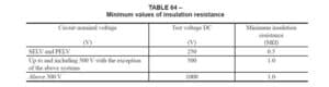
The IET Wiring Regulations sets out the values of test voltages and minimum insulation resistances for different types of installation in Table 64. This table is re-produced below.
The minimum values of insulation resistance are for a main switchboard or a distribution circuit with all its final circuits connected.
For a new installation, without current using equipment and electronic devices connected, insulation resistance measurements should far exceed the minimum values set out in Table 64.
The Test Process.
For a new 230/400V installation set the insulation resistance tester to 500V for the first insulation resistance test. Carry out a test between all live conductors and then all live conductors connected together and earth, see Regulation 643.3.1. When carrying out the tests leave the test leads connected to the installation after releasing the test button to ensure any capacitive charge of the installation is discharged before the leads are disconnected.
Following the connection of current using equipment and electronic devices a second insulation resistance test must be carried out. Set the insulation resistance tester to 250V and carry out the test between all live conductors connected together and earth. The insulation resistance value should be at least 1MΩ.
A Note to Regulation 643.3.3 recommends checking with equipment manufacturers instructions to verify if their equipment should be disconnected for a 250V DC insulation resistance test.

Post Test.
Immediately re-connect the supply neutral. Re-connect the SPD or replace the SPD modules. Re-connect any metering connections. Record the test results on the Schedule of Test Results form.
More News Articles