Guidance notes 3: Why top level MFT’s are worth the premium.
With the introduction of guidance notes 3, we explain why sometimes it pays to invest in an advanced MFT.
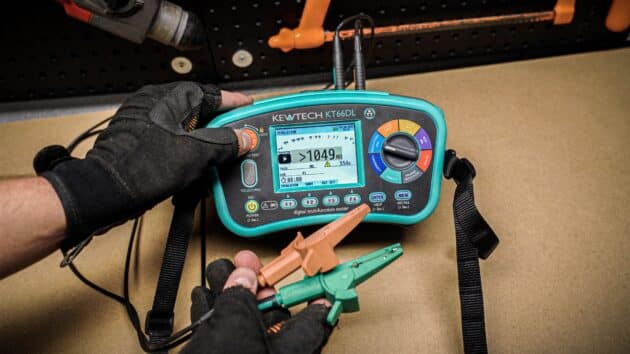
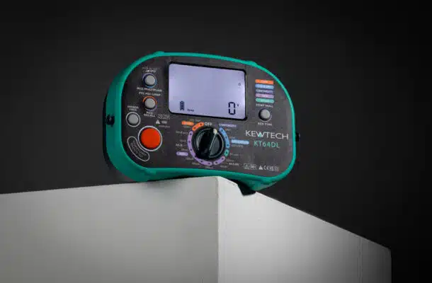
To many, the quality of an MFT installation tester is all down to the quality of the loop impedance function. Over time we have increased our usage of non-resistive loads which has brought problems with electronic noise and harmonics. We also have sophisticated RCDs, control devices and now super sensitive EV charging equipment. All these influences require greater sophistication in our test equipment. The Kewtech KT66DL has six loop test options that can tackle all eventualities. Starting with it’s unique 25 A high current test to give an accurate 0.001 Ω resolution loop measurement for Ze measurements when in close proximity to the source.
Section 2.6.16 of the IET Guidance notes 3 highlights the importance of determining the Prospective fault current and the difference between resolution and accuracy. A 0.01 Ω resolution test on some testers may only be reliable at 0.1 Ω and above meaning a variance of between 23 kA and 2.3 kA. Due to the nature of the KT66DL high current test it is one of the few testers to be able to give a genuine 50 kA PSC range.
Section 4.5 of the Guidance notes 3 lists issues connected to loop impedance testing. These include electrical noise, harmonics, RCD uplift and test lead contact resistance and resolution / accuracy of the instrument when installations are at close proximity to the source transformer. The challenge with all these is particularly acute for low current testing, the KT66DL mitigates all these factors having well developed systems and algorithms developed by a design team that has over 45 years’ experience in loop testing including the Robin D-lok, if you’re old enough to remember the first non-trip loop tester.
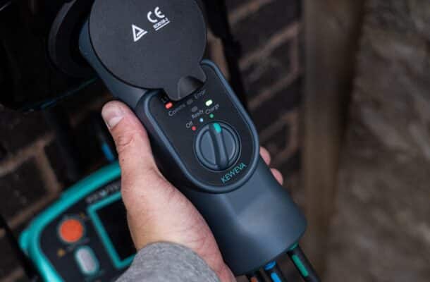
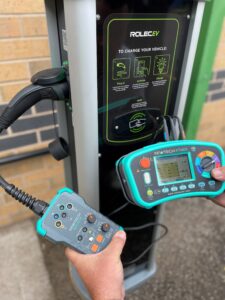
The KT66DL has two special loop tests for EV charging equipment, these overcome ones that are sensitive to tripping under the standard tests. There is also a very stable and repeatable low current two wire test. This has great advantages when testing lighting circuits, as with this setting loop impedance tests can be conducted at a light switch where only the switched live and earth available.
In section 2.6.28 in the IET Guidance note 3 it recommends method 1 that all RCDs are disconnected whilst the test is being conducted. As the supply current follows a sinusoidal wave form the current is constantly rising and falling. Your MFT must determine when the RCD trips and the voltage falls to zero. In the case where the loads have large non-resistive components the voltage may be held up significantly which can give spurious results. A quality MFT will be able to account for these anomalies by predicting what the wave should be and detecting the break point accurately – the better the tester the better the performance here.
The IET point out that the Wiring Regulations represent the minimum standards and as such recommend that all RCDs are tested at x 1 I∆n with a type AC test at both 0⁰ and 180⁰ but it also give options for other RCD testing including fault finding. The guidance notes point out different scenarios depending on RCD type and rating. To satisfy these, the KT66DL has a comprehensive RCD function including a variable RCD setting.
The more straightforward tests for a multifunction tester are the dead tests where the circuits under test are not energised. The recommendations with amendment 2 clearly identify where 500 V and 250 V insulation testing should be conducted and promotes the installation of SPD devices. The KT66DL includes an SPD test which does not diminish the life of SPD due to the low-level energy of the test.
So, whether it’s to overcome the issues raised in Guidance notes 3 such as electrical noise and RCD uplift, or determining the prospective fault current requiring a PSC range of over 20kA, the importance of using a tester that’s fit for purpose with the functions required to meet current recommendations cannot be understated, even if that means having to pay a little more for that piece of mind.
More News Articles
31 Oct 2024
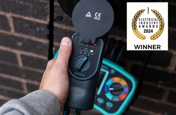
KEWEVA WINS PRODUCT OF THE YEAR!