The Measurement of Prospective Fault Current.
What is Prospective Fault Current?
Fault Current is defined in Part 2 of BS 7671 as, “A current resulting from a fault”.
Part 2 of BS 7671 also defines Prospective Fault Current (Ipf) as, “The value of overcurrent at a given point in a circuit resulting from a fault of negligible impedance between live conductors having a difference of potential under normal operating conditions or between a live conductor and an exposed-conductive-part”. So, in essence we are considering the magnitude of the current that will flow under a fault condition such as a short circuit between live conductors, perhaps through cable damage, or where a live conductor or live part has shorted to an exposed conductive part causing it to become live.
Why do we need to assess Prospective Fault current?
Part 1 of BS 7671 sets out the Scope, Object and Fundamental Principles for the Regulations there is a requirement in regulation 133.2 to select equipment that can handle the maximum steady current in normal service and the current in abnormal conditions and the period (e.g., the operating time for protective devices, if any) during which it may be expected to flow. In addition, The Electricity at Work Regulations 1989 (EAWR) in Regulation 5 says, “No electrical equipment shall be put in to service where its strength and capability may be exceeded in such a way as may give rise to danger”.
So, we need to calculate and/or measure fault current to ensure that equipment, and equipment means any electrical equipment we install, to ensure that it can handle currents in normal service and also under fault conditions where excessive current may flow without causing danger. Danger meaning the risk of injury to persons and livestock through fire, shock and burns due to arcing and explosions. Therefore, circuit and prospective earth fault current shall be measured, calculated or determined by another method, at the origin and at other relevant points in the installation. A circuit breaker not sufficiently rated for the prospective short circuit current may weld the contacts together or cause the moving parts to fail and not disconnect under an earth fault condition putting persons in danger of electric shock. The protective device may disintegrate or explode and start a fire due to not sufficiently rated to safely disconnect the prospective fault current.
In Part 6 of BS 7671 (Inspection and Testing) there is a requirement in Regulation 643.7.3.201 that says, “The prospective short circuit current installation and prospective earth fault current shall be measured, calculated or determined by another method, at the origin and at other relevant points in the installation”. Calculation of fault current is useful but it may be difficult to gather all the data to enable the calculation to be performed. For example, determining the earth fault path impedance would be difficult due to unknown parallel paths lowering the overall impedance of the known protective conductors. For this reason, measurement of prospective fault current is to be preferred.
Using the measured prospective fault current will enable an assessment to be made to ensure that equipment, such as distribution boards and protective devices, is suitably rated for the maximum prospective fault current.
High fault currents are a good thing as they speed up disconnection times and enable maximum earth loop impedance (Zs) values to be achieved to ensure automatic disconnection in the required disconnection time for fault protection.
Fault Current Ratings
Switchgear, distribution boards and consumer units will be rated for extremes of fault current for a certain period of time, for example a switchboard may be rated for 50kA for 1s. The protective devices inside the switchboard would need to be rated for 50kA to ensure they can safely disconnect the supply under fault conditions if required to do so with respect to the prospective fault current.
BS EN 60898 circuit breakers will be marked to shown their maximum short circuit ratings which will be an indicated number in a box on printed on the device. This number is the Icn rating which is the maximum short circuit capacity that the device can safely interrupt but may not be usable after it has operated. Manufactures may also indicate the Ics rating which is the maximum short circuit rating that the device can interrupt without any loss of performance.
Older obsolete BS 3871 circuit breakers will be marked with an “M” number for example M3 meaning a short circuit rating of 3kA.
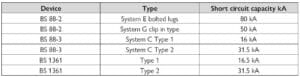
Other fault current ratings for typical protective devices are shown in the table below.
Safety
The measurement of Prospective fault Current is a live working activity which requires working on or near live conductors. Regulation 14 of the EAWR permits this activity if it is “reasonable in all circumstances for him to be at work on or near it while it is live”.
Before carrying out this live testing a formal risk assessment (RA) must be undertaken to assess all the risks that may be present on the particular site the testing is going to be carried out. Electric shock and arc flash risks will be present and these need to be evaluated not only to the person carrying out the tests but to others assisting that person, others nearby and users of the installation who may be impacted by the testing activity. From the risk assessment a method statement will need to be produced by a competent person. Essential to the method statement will be the competence of the person carrying out the testing in terms of qualifications to carry out the task, experience and assessment of capability with evidence of ongoing training and assessment.
Consideration should be given, depending on the risks, for the wearing of PPE such as full-face flash protection, flame retardant overalls and gloves.
Preventing other people from entering, or being nearby the area, where the testing is being carried out must form part of the method statement and may include exclusion from the work area by the use of barriers and the erection of warning signs.
The HSE publication HSG 85 Electricity at Work Safe Working Practices and the HSE Safety in electrical testing at work guidance document, which are both free to download from the HSE website, provide essential safety guidance for people undertaking electrical testing. The Institution of Engineering and Technology (IET) Guidance Note 3 Inspection and Testing is an essential guidance document for anyone engaged in the inspection and testing of Low Voltage electrical installations.
Instrument selection
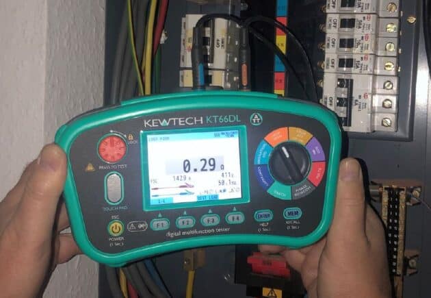
Selecting the correct type and rating of the test equipment to be used that complies with BS EN 61557 is essential for the safety of the user and others who may be impacted by the testing process. BS 7671 Regulation 643.1 requires instruments used to comply with the relevant parts of BS EN 61557. The Kewtech KT66DL Multifunction Tester (MFT) meets the requirements of BS EN 61557 Parts 1,2,3,4,5,6,7 and 10.
The instrument to be used must be rated for the maximum voltage present on the installation. The Kewtech KT66DL MFT is rated in accordance with IEC 61010-1 Cat IV 300V and CAT III 600V so can safely be used on single phase and 3 phase electrical installations.
Verifying the instrument, leads and probes are undamaged and are in good condition immediately before use is essential for the safety of the person using the equipment and others who may be nearby. The use of test leads, clips and probes complying with the Health and Safety Guidance document HSE GS 38 should be a minimum requirement in all cases. Kewtech leads, clips and probes meet and exceed the requirements of HSE GS 38.
For testing on, or near, high current supplies fused probes should be used fitted with fuses. These fuses should be ceramic HBC fuses not ordinary glass fuses. Kewtech’s ACC070 fused probes provide a high level of protection to the user when taking measurements on low impedance high current circuits. Even with fused probes fault current testing must be performed downstream of supply circuit protection.

Single phase fault current testing
To verify the maximum on single phase circuits 2 tests, need to be undertaken. A 3-lead test can be undertaken or some instruments are capable of 2 lead tests. The KT66DL will do both 2 and 3 lead fault current testing. The correct range on the instrument must be selected before commencing testing.
A test must be undertaken between line and neutral and the result recorded. Then a second test undertaken between line and earth and the test result recorded. The highest of the 2 recorded results will be the maximum prospective fault current and this result entered on to test certificate or report.
3-Phase fault current testing
For 3-phase testing an instrument rated for 400V must be used. The KT66DL is rated for CAT 3 600V. The maximum prospective fault current on a 3-phases circuit would be a fault of negligible impedance where all 3-line conductors are shorted simultaneously. Simultaneously shorting all 3-line conductors and earth and neutral will not increase the prospective fault current.
For this test 3 tests will need to be undertaken. The correct range on the instrument must be selected before commencing testing. The 3 tests to be undertaken are all 3 lines to neutral and record each result. Then take the highest of the 3 readings and double that result. This calculated reading will give a “rule of thumb” result that may be recorded on certificates and reports. This calculated reading will overstate the fault current.
For a more accurate and representative reading a further set of tests can be undertaken. Ensure the instrument selected is cable of testing line to line i.e., 400V or more. Using the KT66DL select the L/L range on the instrument. Then measure between all line conductors e.g., L1 to L2, L1 to L3 and L2 to L3 and record the results. Select the highest of the 3 results and divide by 0.87. This calculated result will be more accurate and lower than the line to neutral X2 result.
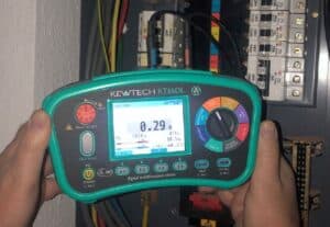
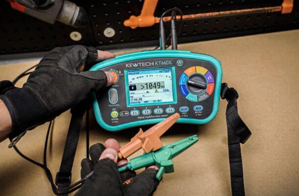
The Kewtech KT66DL in loop setting with an L1 to L2 loop test result
Interpreting the test results.
The measured results are an indication of prospective fault current but they will not be the precise prospective fault current. The actual fault current may be limited by the ability of the source of supply to deliver the calculated or measured fault current. Under short circuit conditions a supply from an HV/LV transformer cannot deliver unlimited fault current as the HV supply voltage may be attenuated by the short circuit on the LV side. Generators may slow or stall under short circuit conditions. In addition, upstream circuit protection will have a current limiting effect which further reduces fault current and voltage drop on supply conductors will also limit fault current. The upstream circuit protection limiting fault current is known as backup protection. If the measured test result is lower than the fault current ratings than the installed equipment no further action needs to be taken. If the measured prospective fault current exceeds the fault current of the installed equipment a further investigation needs to be carried out before declaring that the installed equipment is not suitably rated for prospective fault current.
An example of where upstream circuit protection may be considered to limit fault current is on single phase domestic and similar installations. Where a modern consumer unit is installed complying with BS EN 61439- 3, and the service cut out fuse is a cartridge fuse complying with BS 1361 or BS 88-3 not exceed 100A, and the consumer unit is fitted only with the manufacturer’s devices, BS EN 61439-2 Annexe ZA then determines the enclosure and protective devices may be considered to be 16kA fault current rated. This is an example of back up protection provided by the cut-out fuse.
More News Articles