EV Charge Point Testing – A Quick Guide
A Quick Guide on how to test EV charging points with the KEWEVSE.
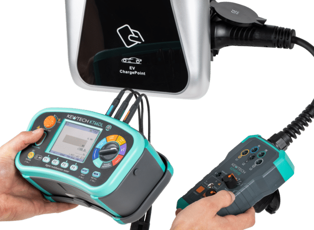
The KEWEVSE is a universal EV charge point testing adapter and can be used with most MFT’s of all brands, however the example below is explained using the KT66DL.
Connecting up:
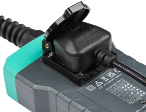
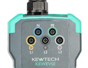
The KEWEVSE can be connected to the KT66DL either by using the socket on the rear of the KEWEVSE or with the distribution board leads to the front. For three phase charge points the distribution boards leads need to be used.
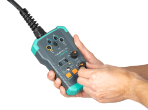
Proximity Pilot (PP) State (Current Simulation)
1. PP State simulates the full load current of the charger.
Turn the PP State rotary switch (8) to the maximum charging current capacity of the charger, generally 32A (7.0 kW). Leave in this position during the following tests.
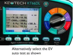
Control Pilot (CP) State (Vehicle/Load Simulation)
2. CP state simulates various charging states. Tests are selected using the CP State rotary switch either rotating clockwise through tests A, B and C, or anticlockwise through tests A, B and D. A,B,D is used when the battery system being charged requires ventilation. This is rare in most of the latest situations. The tests are:
A) Simulates open (electric vehicle not connected)
B) Simulates electric vehicle connected but charging not required
C) Simulates electric vehicle connected and charging (in this state there may be a delay before charging begins).
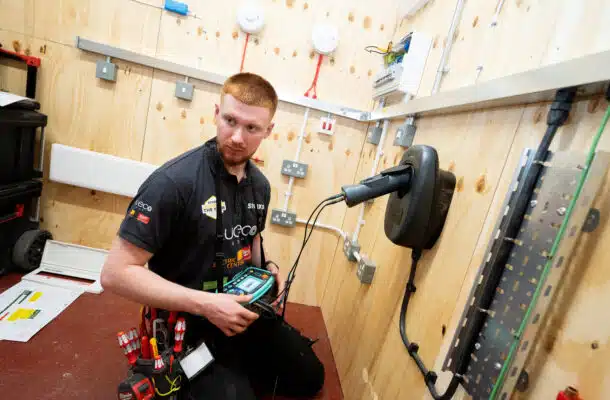
Assuming it is a 32 A charger, turn PP state to 32 A. With the CP state in position A then B then C allowing time for the charger to settle in each case, the charging point should change its status in each position. All charging points are different, some will have a flashing LED to show this change of status, others will change an LED colour, it depends on the EV charge point.
In position C when simulated charging begins, it will generally be possible to hear the contacts closing. At this point the electrical safety tests can be carried out – earth loop impedance, the 6 mA RDC-DD test and Type A, Type F or Type B RCD test.
Note: Each time the charger trips the resetting procedure varies across charging point brands and model. With some, you must turn the CP state back to A and others the CP state position can stay in position C. Some charging points have proved to be very sensitive to the loop test current and have tripped before the test has been conducted. The KT66DL has a special low current test for EV charging points if this is the case.
The KEWEVSE can also simulate a CP Error (earth fault) and PE Error (broken PE conductor). If these buttons are pressed when in test position C the charge point should stop charging.
Residual Direct Current Detecting Device (RDC-DD) 6mA Test, and Type A, Type F or Type B RCD Testing.
These tests are to ensure that the RDC-DD, if installed in the charger, trips when any pulsating DC component superimposed on the AC supply waveform is 6mA or above; and to ensure that Type A, F or B RCDs on either the charging unit or the charger final circuit complies with BS EN 61008 or BS EN 61009 as appropriate.
Note: BS 7671:2018+A2:2022 now requires all RCDs, Types AC, A, F and B to be tested in the same way, with the instrument set to Type AC RCD, and applying the IΔn x1 test.
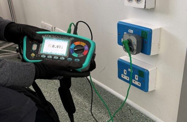
3. Connect the KEWEVSE into the charge point and the KT66DL into the rear of the KEWEVSE via the
socket using the mains lead (or use the instrument individual leads to connect to terminals 1, 2 and 3 on
the front).
RDC-DD Test
Set the KT66DL to RCD and select Type EV, x1, DC 6mA and press Test.
The device must trip within 10s (seconds). See IEC 62955:2018, Table 2.
RCD Test for all RCD Types
Set the KT66DL to Type AC, x1, 30mA and press Test.
See Regulation Group 643.7.
The device must trip within 300ms (milliseconds).
CP and PE Signal Output terminals
CP and PE signal output terminals (4) would not generally be used for routine testing of a charging point, but are provided in case a more in depth check of the charging unit is to be carried out using an oscilloscope, which can be connected to the KEWEVSE via the test cable provided.
Charging Point Final Circuit
BS 7671:2018+A2:2022 also requires Initial Verification inspection and testing to be carried out on the charger final circuit if a new installation, and an Electrical Installation Certificate to be issued to the person ordering the work.
More News Articles
18 May 2026
Learner of the Year 2026!